Analyzing Circuits
(aka Even More Fun with Resistors)
This article introduces basic circuit analysis using Kirchoff's laws. These
techniques can be a bit confusing at first, but with practice should become
clear and simple to use. Simple resistors are used for the examples, but the
technique applies to numerous types of electronics devices.
Kirchoff's Laws
Ohm's Law (V=IR) is one of the basic rules necessary for understanding
circuits. In order to understand more complex circuits, two more rules are
necessary, and these are referred to as Kirchoff's Laws, after Gustav Kirchoff,
who first published them in 1848.
- Kirchoff's Current Law: The sum of all currents entering a node equals
zero.
- Kirchoff's Voltage Law: The sum of all voltages around any closed path in
a circuit equals zero.
In order to understand these, we first have to understand the concept of a
node and a circuit path.
Nodes and Paths
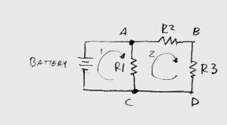
The following schematic shows a battery connected to three resistors. Two of
these resistors are in series, and the series pair is in parallel with the third
resistor. A node is, basically, any circuit connection. This circuit has 3
nodes, labled A, B, and C in the circuit. Note that the point labled D is not a
node, but instead is part of the same electrical connection as node C. Node A
has the positive terminal of the battery, the top end of R1, and the top end of
R2 connected to it. Node B has the bottom of R2 and the top of R3 connected to
it. Node C has the negative terminal of the battery, the bottom end of R1, and
the bottom end of R3 connected to it. Note also that there are numerous ways of
drawing a schematic that convey this same information.  This circuit also has two closed
paths shown, indicated by the arrows and the numbers 1 and 2. There is a third
path which is not shown, that basically goes around the perimeter of the
circuit. A closed path has to form a loop, returning to the point where it
started.
Kirchoff's Current law is fairly intuitive once you understand what a node
is. A node isn't going to create energy, nor is it going to make energy
disappear into nothingness. A node is a simple electrical connection. If we take
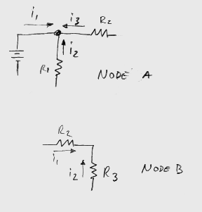
a close look at node A, we can see three currents that go into node A, labled
i1, i2, and i3 in the following diagram.  Note that we have drawn i2 and i3 as
going into the node. Because the battery is the source in the circuit and the
resistors are absorbing power, it will turn out that i2 and i3 will both be
negative numbers. This means that the current is actually flowing in the
opposite direction from what the arrows show. Intuitively, this means that all
of the current from the battery will be split into R1 and R2 (after all, where
else is it going to go?). If we look at node B, we have two currents going into
the node. Since there are only two currents, they must be equal in magnitude but
opposite in sign.
     i1+i2=0
     i1=(-i2)
Intuitively, this means that all of the current flowing into the node from
R2 has to flow out into R3. R2 and R3 will have the same current flowing through
them. In fact, any number of circuit elements in series will always have the
same current flowing through all of them, since at any node in the series you
can sum the currents to zero. Intuitively, if you look at the node, if you have
current coming out of R2, where is it going to go? It only has 1 place to go,
and that is into R3, so it should make sense that everything coming out of R2
goes into R3.
Node Voltage Analysis
As the name suggests, this method looks at the voltages on each node to solve
the overall circuit. At each node, we use Kirchoff's Current Law and Ohm's Law
to determine voltages. This will give us a bunch of simultaneous equations that
we can solve using good old basic algebra. You will end up with a number of
equations equal to the number of nodes, so for complex circuits this can lead to
quite a bit of math.
As an example, let's use our circuit from above with the following values.
The battery is 6 volts, R1 is 1000 ohms (usually written as 1K), R2 is 2000 ohms
(2K) and R3 is 4000 ohms (4K). The voltages at nodes A, B, and C will be written
as Va, Vb, and Vc. The first thing we need to do is choose a voltage reference.
Voltage at a point is meaningless. Voltage is always between two points.
Therefore, we choose a common reference for the entire circuit, and base all of
our other voltages from this point.
IMPORTANT: Where we choose our voltage reference is completely arbitrary, and
the voltage we choose to assign it is also arbitrary.
We have three nodes to choose from as our reference. We can pick any of the
three, and can assign it any value we want. However, if we pick point B and give
it the arbitrary value 4007.335, then when we start plugging though the math we
will quickly find that 4007.335 is not a very wise choice. Picking a point and
calling it zero is a much better choice, since X-0 is a lot easier than
computing X-4007.335. As a practical matter, when we design circuits we
generally have all sorts of signals that interact with each other, and to make
the design a lot simpler, they all share a common signal return. It is therefore
most convenient to choose this signal return as our zero reference.
In our example, the current goes out from the positive terminal of the
battery and returns to the negative terminal of the battery. It is easiest for
us to use point C as our zero reference. You will often find that the negative
terminal of the supply is the most convenient zero reference, and so our example
is fairly typical in this respect. Vc therefore equals zero.
Now that we know the voltage at C (since we arbitrarily picked Vc to be our
zero), we now need to determine the voltages at points A and B. Node A is easy
to determine, since we have a voltage source connected between A and C. The
voltage source will hold a constant voltage between these two points, and in our
example this is 6 volts. So, no matter what the voltage is at C, the voltage at
A will be C+6. Since C is zero, this addition is trivial, and A is 6 volts. Had
we chosen 4007.335 as our reference (not a good idea), then A would be
(4007.335+6) or 4013.335 volts. Obviously, 0 is a lot easier to add.
Now we have the voltage at point B to determine. Using Kirchoff's Current
Law, we have two currents that sum to zero at node B. The first current is the
current through R2, and the second is the current through R3, which we will call
i2 and i3. Ohm's Law says that the voltage across a resistor is V=IR. The
voltage across R2 is Va-Vb. The voltage across R3 is Vc-Vb (note that the
direction of the current corresponds to which term comes first). So, let's start
with Kirchoff's Current Law and substitute in these values using algebra.
     i2+i3=0                     (Kirchoff's Current Law)

     i2=(Va-Vb)/R2               (Ohm's Law, rearranging V=IR)
     i3=(Vc-Vb)/R3

     (Va-Vb)/R2+(Vc-Vb)/R3=0     (substitute i2 and i3 into the first equation)

     (6-Vb)/2000+(0-Vb)/4000=0   (substitution)
     (6-Vb)/2000 = -(0-Vb)/4000
     2(6-Vb) = Vb
     12-2Vb = Vb
     12 = 3(Vb)
     Vb = 4
We can now solve for individual currents through the resistors using Ohm's
Law. We will use i1, i2, and i3 to represent the currents through R1, R2, and R3
respectively.
     6=i1 (1000)
     i1 = 6/1000 = 0.006 amps = 6 mA

     i2 = (Va-Vb)/R2 = (6-4)/2000 = 0.001 amps = 1 mA

     i3 = (Vc-Vb)/R3 = (0-4)/4000 = -1 mA
Note that i3 was chosen as going into node B. Had we chosen it to go in the
opposite direction, then it would have turned out to be a positive 1 mA. Also
note that i2 and i3 would be identical in that case. This illustrates the fact
that all components in series have the same current passing through them.
For more complex circuits, we simply go node by node and write all of the
equations arising from Kirchoff's Current Law. This will lead to a set of
simultaneous equations that can be solved using algebra. 
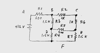
This circuit is much more complicated. It has 6 nodes, labled A through F. To
solve this, we simply use the exact same method as above. Similar to the above
example, we will choose node F as our zero reference.
    Vf=0
    Va=12

    Using Kirchoff's Current Law:
    (Vb-Va)/R1 + (Vb-Vd)/R3 + (Vb-Vc)/R2 = 0   (Node B)
    (Vc-Vb)/R2 + (Vc-Ve)/R6 + (Vc-Vf)/R8 = 0   (Node C)
    (Vd-Vb)/R3 + (Vd-Ve)/R5 + (Vd-Vf)/R4 = 0   (Node D)
    (Ve-Vd)/R5 + (Ve-Vc)/R6 + (Ve-Vf)/R7 = 0   (Node E)
We know Vf and Va, and we now have 4 equations with 4 unknowns (Vb, Vc, Vd,
and Ve). If we plug in all of the values, we end up with these four equations.
    (Vb-12)/600 + (Vb-Vd)/1500 + (Vb-Vc)/1000 = 0   (Node B)
    (Vc-Vb)/1000 + (Vc-Ve)/1000 + (Vc-0)/3000 = 0   (Node C)
    (Vd-Vb)/1500 + (Vd-Ve)/500 + (Vd-0)/1500 = 0    (Node D)
    (Ve-Vd)/500 + (Ve-Vc)/1000 + (Ve-0)/2500 = 0    (Node E)
Now, all that is needed is some basic algebra, and the circuit can be
completely solved. Since the solution is rather lengthy (although not all that
complex), it is left as an exercise to the reader.
Once all of the voltages have been solved, you can easily determine the
current through any single resistor by using Ohm's Law and the voltage
difference of the two nodes that the resistor is connected to.
Mesh Current Analysis
Mesh current analysis relies on Kirchoff's Voltage Law to arrive at the exact
same solution that you would get using node voltage analysis. Both mesh current
and node voltage are valid methods for solving a circuit. They just approach the
problem in slightly different manners.
As with node voltage analysis, the solution involves breaking down the
circuit into individual parts and writing the equations for them, then combining
the several different equations to form a complete solution. The complexity of
the analysis is the same as node voltage analysis for the same circuit, so there
is no simplicity advantage in using either method.
Kirchoff's Voltage Law states that for any given loop in a circuit, the
voltage around the loop sums to zero. We will now solve the exact same problem
in the above example, using this method. Here again is our circuit. 
The two currents we will use are shown by the arrows and the numbers 1 and 2.
For this analysis we will call these i1 and i2, but note that our designations
for i1 and i2 are different than what we were calling i1 and i2 in the previous
example.
We are going to assume that all of these currents "mesh" together. The
current through R2 and R3 is going to be i2. The currents mesh together through
R1, which means that the current through R1 will be i1+(-i2). Note that i2 is
negative since it is in the opposite direction of i1.
Now we use Kirchoff's Voltage Law and sum up the voltages around each loop.
The battery provides a voltage rise (positive) which is constant, while
resistors will provide a voltage drop (negative) given by Ohm's Law, V=IR.
   +6 - (i1-i2)R1 = 0             (Kirchoff's Voltage Law for loop 1)
   - (i2-i1)R1 - i2R2 - i2R3 = 0  (Kirchoff's Voltage Law for loop 2)

   6 - 1000(i1-i2) = 0            (using algebra on the loop 1 equation)
   1000i1 - 1000i2 = 6

   (i2-i1)R1 + i2R2 + i2R3 = 0    (using algebra on the loop 2 equation)
   1000i2 - 1000i1 + 2000i2 + 4000i2 = 0
   1000i1 = 7000i2
   i1 = 7i2

   1000(7i2) - 1000i2 = 6
   6000i2 = 6
   i2 = 0.001 = 1 mA

   i1 = 7(i2) = 7 mA
The current through R1 is (i1-i2) or 6 mA. The current through R2 and R3 is
i2, or 1 mA. This is exactly the same result that we got from the node voltage
analysis above. We can use Ohm's Law to calculate the voltage drop across R2,
which is simply 0.001(2000) or 2 volts. Therefore, the voltage at node B is
(6-2) = 4 volts (remember that node C was our reference zero, and node A was
determined to be 6 volts by the presence of the voltage source).
Using Node Voltages and Mesh Currents on more complex circuits
The techniques described above use simple resistors, but can be used with
more complex circuit elements as well. This may mean that more difficult circuit
equations are used, and when capacitors and inductors are introduced into the
circuit may mean that a bit of calculus is required. Since the average hobbyist
probably doesn't know calculus, they will be unable to solve these equations,
and in this case must hope for an intuitive understanding of the circuit, since
a mathematical solution is beyond their means.
Large, complex circuits will result in large sets of simultaneous equations
to be solved. This, too, may lead to more math than the hobbyist really desires
to use. Fortunately, this much of an in-depth circuit analysis is usually not
necessary, especially in the modern era of integrated circuit chips.
For cases where the math is a bit too intense, or the circuit is just too
large, one of the computerized simulator packages like Spice (and all of its
variations) can be quite valuable for yielding a solution with a minimal amount
of effort.
These techniques are only tools. They can aid in understanding a circuit, but
are not absolutely required for a hobbyist level of understanding. As with all
tools, they won't do you much good if you never learn to use them properly. But,
if you take the time to learn and apply them, they can come in handy from time
to time.
 This circuit also has two closed
paths shown, indicated by the arrows and the numbers 1 and 2. There is a third
path which is not shown, that basically goes around the perimeter of the
circuit. A closed path has to form a loop, returning to the point where it
started.
 Note that we have drawn i2 and i3 as
going into the node. Because the battery is the source in the circuit and the
resistors are absorbing power, it will turn out that i2 and i3 will both be
negative numbers. This means that the current is actually flowing in the
opposite direction from what the arrows show. Intuitively, this means that all
of the current from the battery will be split into R1 and R2 (after all, where
else is it going to go?). If we look at node B, we have two currents going into
the node. Since there are only two currents, they must be equal in magnitude but
opposite in sign.