Diodes
This article describes the basics of diodes.
Diodes are devices that conduct electricity in one direction, but not in the
other, sort of like a one way valve for electricity. Diodes can actually be made
in several ways, although these days most hobbyists will only see the
semiconductor version. Diodes are often called rectifiers, since one of their
uses is to rectify AC voltage into DC.
Semiconductors are generally fabricated out of two types of silicon, called N
and P type. These are actually created by adding certain impurities to silicon.
A single PN junction creates a diode. Using three layers will make a bipolar
junction transistor, of which there can be two types, NPN or PNP. Transistors
will not be discussed in this article.
Voltage and Current in Diodes
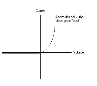
Unfortunately, the relationship between voltage and current in a diode is
somewhat complex and non-linear. This means that you can't use simple algebra
formulas to determine the exact voltage or current like you can with resistors.
The actual voltage and current relationship follows a curve, as shown in the
following diagram:  To make things a bit more
simple to deal with, we usually approximate this relationship. The simplest
approximation is to treat the diode as an ideal diode, meaning that it lets
electricity flow in one direction without having any other effect on the
circuit, and prevents its flow in the opposite direction. This completely
ignores any voltage drop that might be present due to the diode, so this
approximation is only good for some limited cases.
EXAMPLE: Let's assume we have a power indicator circuit for a 12 volt device.
This power indicator circuit is composed of an LED (a light emitting diode) in
series with a resistor to limit the current flowing through the diode. When the
power is on, current will flow through the resistor and the diode, causing it to
light. Let's also assume that the maximum current through the LED should not be
more than 30 mA, otherwise it will become a DED (a dark emitting diode, which is
a somewhat humorous way of referring to a burnt out LED). What size should the
resistor be?
ANSWER: This is one case where a very simple approximation of a diode can be
used. If the diode acts as just a conductor when current is going through it in
the forward direction, then we have 12 volts across a resistor that we want the
current to be limitted to 30 mA. Using Ohm's Law, V=IR, or R=V/I, R=12/0.03, or
R=400 ohms. This means that if the resistor is less than 400 ohms we will burn
out our LED. In the actual circuit, the diode will drop some of the voltage, and
the actual current flowing through the resistor will be slightly less than what
we calculated, but this also gives us some breathing room to handle resistor
tolerances.
More Detailed Models
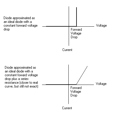
We can make a slightly more detailed model by adding a constant voltage drop
to the diode. This at least gives us some voltage drop, where our earlier
approximation does not. If we want even more detail, we can add a resistor in
series to our model. While still not an exact solution, the following diagram
shows how we are getting closer to the actual voltage and current relationship
in a diode:  As a general rule, the constant
voltage drop model is sufficient for most electronics circuits. WARNING: Be
careful when using this model, however. A lot of hobbyists end up with the
misconception that diodes always have a set voltage drop across them, no matter
what the current. This is definately not true. For the actual voltage drop, you
have to look at the current-voltage curve for the particular diode you are
using. It will be similar to the above curve.
Real World Diodes
Diodes will generally be either small signal diodes (where you are trying to
alter a signal of relatively low current) or power rectifier diodes, which do
the same thing, but are designed to handle larger currents. They are packaged in
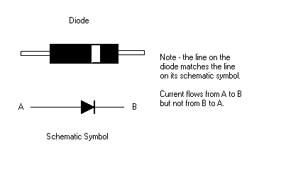
little round plastic cases with a line around one end. The current flows from
the side without the line towards the side with the line. You can also get light
emitting diodes, or LEDs, which generally have one lead longer than the other so
you can tell which way the current flows. Some LEDs are packaged with two LEDs
in parallel, one facing each direction. By applying current in one direction or
the other, different colors can be made. Alternating the direction of the
current and the amount of on/off time for each direction can yield a variety of
colors from what appears to the eye to be a single LED. You can also buy LEDs
packaged with a built in dropping resistor and also with a built in blinking
circuit.  If you are using power diodes,
usually only the maximum current rating of the diode is important. If you are
using a smaller signal diode, usually the voltage drop becomes more important.
In an LED, the current through the diode is more important than the voltage
drop, since the current determines how bright the LED is.
Zener Diodes
In general, we want diodes to be able to handle fairly large reverse voltages
without conducting electricity. This is what makes them useful as diodes - they
conduct in one direction and do not conduct in the other. Some diodes are
constructed so that they break down at a controlled voltage in the reverse
direction. These are called zener diodes.
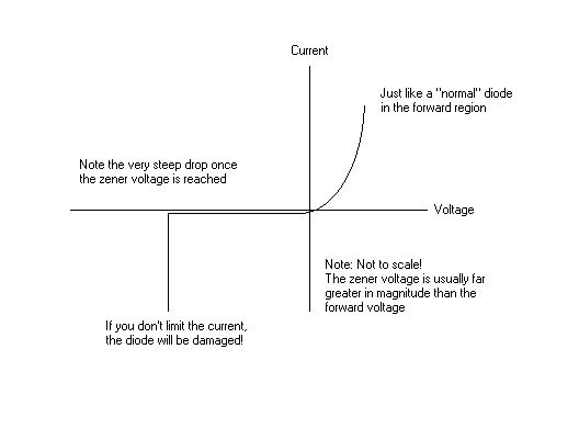
Zener diodes work the same way as regular diodes for most of their operation.
They have a similar voltage and current curve when operated in the forward
direction. The difference comes in the reverse direction. Here, they still act
like regular diodes as long as the reverse breakdown voltage is not exceeded.
However, once you reach the reverse breakdown voltage, the zener diode starts to
conduct electricity, and will continue to conduct electricity while maintaining
the same reverse voltage across its terminals. WARNING: This means that if not
used properly, it is very easy to burn up a zener diode. You must have some
external component to limit the amount of current that flows when the breakdown
voltage is exceeded. 
Why would we be interested in having a diode that breaks down in the reverse
direction? At first this might seem like a rather useless device, but in fact it
has many uses. You can use a zener diode to limit the voltage at a certain point
in a circuit, thus protecting an input. Since the breakdown occurs in a very
controlled way, you can also use zeners to make a known voltage source, which is
constant over a wide range of power supply voltages. This has applications for
circuits that need some sort of reference to make measurements by, and also to
make regulator circuits for power supplies.
Actually, just to be clear, a normal silicon diode will also break down if
you put enough of a reverse voltage across its leads. The difference is that
normal diodes are designed to have a very high reverse breakdown voltage, but
zener diodes are designed to have a very low (and much more controlled) reverse
breakdown voltage.
Some Practical Diode Circuits
![]()
 To make things a bit more
simple to deal with, we usually approximate this relationship. The simplest
approximation is to treat the diode as an ideal diode, meaning that it lets
electricity flow in one direction without having any other effect on the
circuit, and prevents its flow in the opposite direction. This completely
ignores any voltage drop that might be present due to the diode, so this
approximation is only good for some limited cases.
 As a general rule, the constant
voltage drop model is sufficient for most electronics circuits. WARNING: Be
careful when using this model, however. A lot of hobbyists end up with the
misconception that diodes always have a set voltage drop across them, no matter
what the current. This is definately not true. For the actual voltage drop, you
have to look at the current-voltage curve for the particular diode you are
using. It will be similar to the above curve.
 If you are using power diodes,
usually only the maximum current rating of the diode is important. If you are
using a smaller signal diode, usually the voltage drop becomes more important.
In an LED, the current through the diode is more important than the voltage
drop, since the current determines how bright the LED is.
