Fun With Resistors
This article covers parallel and series resistance, color codes, and the
different types of resistors that you can buy. It assumes that the reader is
already familiar with the basic concepts of voltage, current, and resistance.
Series and Parallel Resistors
When you have components in series, the current through them is always
identical. Likewise, when you have components in parallel, the voltage across
them is always identical.
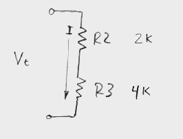
 Here, we have R2 and R3 in
series. The current through R2 is the same as the current through R3 (otherwise
this would violate Kirchoff's Current Law at node B). The voltage across both R2
and R3 can be easily determined by adding the voltage across each resistor. Each
resistor's voltage is determined by Ohm's Law, V=IR. So, the voltage across both
resistors, which we will call Vt (for total voltage) is V2+V3, where V2 and V3
are the voltages across each resistor. Since the same current flows through
both, we will just call it I.
   Vt = V2 + V3
   V2 = I (R2)            (Ohm's Law)
   V3 = I (R3)
   Vt = I(R2) + I(R3)
   Vt = I(R2+R3)
This means that the total voltage equals the current multiplied by the sum
of the resistances. In other words, the two resistors are acting together as if
they were one big resistor equal to R2+R3. R2 and R3 together draw 1 mA. If we
were to replace R2 and R3 with a single resistor equal to their sum
(2000+4000)=6000 ohms, then that resistor would also draw 1 mA (I=V/R, V= 6
volts, R=6000 ohms).
If we had a little black box connected to the circuit, we would not be able
to tell if it had the two resistors shown inside of it (R2 and R3) or if it had
a single 6000 ohm resistor inside of it. It might contain any number of
resistors whose sum totalled 6000 ohms. This fact is important, because often we
want a certain resistance, and available resistors do not provide this value.
All we need to do is find two smaller resistors that total our desired value,
and we have an equivalent that will work in our circuit.
Resistors in parallel have the same voltage across both resistors, but the
currents will be different. If we rearrange Ohm's Law into the form I=V/R and
apply Kirchoff's Current Law we can determine how resistors act in parallel.
  Itotal=I1+I2    (from Kirchoff's Current Law)
  I1=V/R1
  I2=V/R2

  Itotal=V(1/R1 + 1/R2)

  Requivalent = V/Itotal = 1/(1/R1+1/R2)
Sometimes this is easier for people to remember by the admittances. The
admittance is the reciprical of the resistance, and is usually given the symbol
Y. As the following equations show, the admittances in parallel circuit add to
make an equivalent admittance, just as the resistances in a series circuit add
to make an equivalent resistance.
  R=1/(1/R1 + 1/R2)
  1/R = 1/R1 + 1/R2
  Ytotal = Y1 + Y2
These series and parallel equivalences are important, and should be
memorized. These formulas will get a lot of use if you do a lot with
electronics. Using Req for the equivalent resistance, the formulas can be
summarized as follows:
   Series Resistors:   Req = R1 + R2 + ... + Rn

   Parallel Resistors: 1/Req = 1/R1 + 1/R2 + ... + 1/Rn
If you have a bunch of different size resistors in series, and one of them is
larger than the others, then it will have the largest effect in determining the
overall resistance. Likewise, if you have a bunch of resistors in parallel and
one of them is significantly smaller than the others, then it will have the
greatest effect on the overall resistance.
Voltage Dividers
Two resistors in series can be thought of as a voltage divider. They will
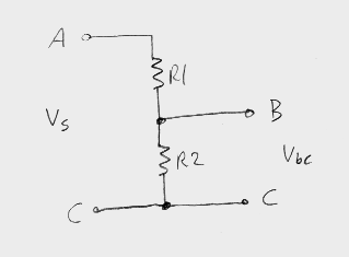
divide the voltage between them.  In this circuit, we have 3 nodes (A, B, and C). The output of the circuit is the
voltage between B and C. If you solve this circuit, you end up with Vbc =
(Vs)R2/(R1+R2).
   Vbc= i(R2)
   Vs = i(R1+R2)
   i=Vs/(R1+R2)
   Vbc=(Vs/(R1+R2) )R2
   Vbc=(Vs)R2/(R1+R2)
In other words, the voltage out is equal to the voltage in multiplied by
the proportion of the lower resistance over the sum of the resistances. The
proportion R2/(R1+R2) is easy to use to derive any desired output voltage (less
than Vs, of course).
The big problem with using this circuit in the real world is that any load
you place on the circuit's output is going to affect the output voltage. For
example, if R1 and R2 were both 1000 ohms, then the output voltage would be one
half Vs. However, if you try to take this output and drive a load with a
resistance of 1000 ohms, then we now have an equivalent resistance of only 500
ohms between nodes B and C (two 1000 ohm resistors in parallel), and the voltage
drops to one third of Vs. This circuit is only useful when the load being driven
from it is significantly higher than R2. One good example of when this circuit
is practical is when driving an op-amp circuit. An op-amp requires a dual supply
(a supply that has both a positive and a negative voltage), but in most typical
circuits the zero voltage is only used for the positive input terminal, which
draws almost no current. Therefore, if you want to drive an op-amp off of a
single supply (like a battery) you can connect the "+" terminal of the battery
to the positive supply pin on the op-amp and the "-" terminal to the negative
supply pin. Then, you use a voltage divider like the circuit above (in fact 1k
resistors work fairly well for an op-amp) to derive the median voltage halfway
between the positive and negative supply, and connect this to the positive input
on the op-amp.
If we are using a 9 volt battery for Vs, the voltage at this node is
(9)(1k)/(1K + 1K) or 4.5 volts above the negative terminal of the battery. But,
remember that which node we choose to call our zero reference is arbitrary. So,
instead of using the negative battery terminal, let's use the output of the
voltage divider as our zero. Now, we have three terminals to consider. We have
the positive terminal of the battery, the negative terminal of the battery, and
the output of the voltage divider. Since we decided that the voltage divider was
our zero reference, the voltage at the negative terminal of the battery is -4.5
and the voltage at the positive terminal is +4.5. We still have a total of 9
volts between the positive and negative terminals, but the point that we are
calling zero has changed.
What we have done is converted a single 9 volt supply into a dual +/- 4.5
volt supply, which is sufficient for most common op-amps like the lm741. This
only works because the current drawn from the voltage divider is very small, and
does not effect the output of the divider. In practice, you should add a 0.1 uF
capacitor between the output of the voltage divider and one of the battery
terminals to make the circuit more immune to noise and transients.
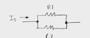
 Similar to voltage dividers,
current dividers use resistors in parallel to divide current. If you have two
resistors in parallel, the current through one is equal to
Is(1/R2)[1/(1/R1+1/R2)]. An example of a practical current divider is an ammeter
(a meter which measures current). An ammeter uses a very low shunt resistance in
parallel with a higher resistance, since the current flow through the higher
resistance would be high enough to destroy the meter element. The current
divider allows a smaller amount of current to be measured, which is within the
meter element's operating range.
Real World Resistors
In the real world, all materials have some resistance. There are times when
we desire a controlled resistance in our circuit. You can buy resistors made
from all sorts of materials, and they are actually quite cheap. The most common
are wire wound resistors, which are nice and cheap but are not well suited to
higher frequency applications (their inductance is too high, and they act more
like an inductor than a resistor at higher frequencies). Other types are carbon
film, metal oxide, and ceramic. You can even buy them in IC packages, since you
often need a bunch of them in a digital circuit to use as pull-up resistors on a
TTL chip's outputs.
The first thing you need to do when selecting a resistor is determine how
much power it is going to dissipate (remember that P=VI, and the previous
chapters have provided numerous methods for calculating V and I). Now, multiply
this number by 2, since you don't want to be driving your resistor to its
absolute maximum ratings, and get a resistor of at least this high of a power
rating, even higher preferred.
The common resistors you will buy for low power work are encoded with several
color bands, usually 4. There are ten colors, which represent the numbers 0
through 9. The last band has a different color, which indicates the tolerance of
the resistor. Because this band does not contain a color on the other three
bands, it is easy to determine which side of the resistor is the start of the
color bands and which side is the end.
To determine the value of the resistor, simply take the first two numbers
(given by the first two color bands), using the first number as the tens digit
and the second as the ones digit, and multiply them by the multiplier indicated
by the third color band. The multiplier is 10 to the power indicated by the
color, so the easiest way to remember it is to use the third band as the number
of zeros. The following table shows the colors and their meanings.
        Color         Value

        BLACK           0
        BROWN           1
        RED             2
        ORANGE          3
        YELLOW          4
        GREEN           5
        BLUE            6
        VIOLET          7
        GREY            8
        WHITE           9

        Tolerance Band

        None            20%
        SILVER          10%
        GOLD            5%
        RED             2%
Here are some examples. A resistor with the four colors Red Red Green Silver
would be a 22 (red red) with 6 (green) zeros after it, or 22,000,000 ohms (22
meg). The resistor has a tolerance of +/- 10 percent, so it may be as low as
19.8 meg or as high as 24.2 meg. A 47k resistor would be marked Yellow Violet
Orange Silver (assuming that it is also a 10 percent tolerance resistor), since
[Yellow-Violet] corresponds to 47 and [Orange] corresponds to 3 zeros.
Some resistors have a fifth band, which is used to indicate its Mil-Spec
(Military Specification) reliability rating. Hobbyists aren't designing
ultra-reliable circuits for weapons systems (at least we hope not), so they
don't generally have to worry about the reliability rating.
Note that when you buy resistors, if you are buying 10 percent resistors they
will not be a "normal" distribution of +/- 10 percent. Many manufacturers
measure the resistance and assign the color bands accordingly. Therefore, you
are almost guaranteed that if you buy a 10 percent resistor, it will be off by
somewhere between 5 and 10 percent.
Variable Resistors and Potentiometers
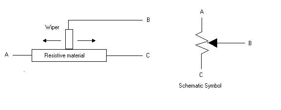
A variable resistor is, as you would expect from the name, a resistor whose
value you can vary. Usually they are made of some resistive material with a
conductor that slides across the top of the material. As you move the conductor
(also called the wiper) the resistance between that conductor and the end of the
resistive material varies. It should be obvious from the following image that as
you move the wiper to the left that the resistance between points A and B
decreases while the resistance between points B and C increases. Conversly, if
you move the wiper to the right then the resistance between A and B increases
and the resistance between B and C decreases. The resistance between A and C is
constant no matter where the wiper is placed. 
Why is the K in the middle?
On many schematics, you will see resistors labled as 4K7 (in other words,
with the K in the middle of the number). This convention comes from the fact
that once you photocopy a schematic a few times on an old photocopier, you can't
tell if the dot is really a decimal point or a dot caused by dust on the copier,
an extra fleck of toner, etc. So, some folks started using the K as the decimal
point. A 4K7 is therefore a 4.7K resistor. This has the advantage that you can
photocopy it a bizillion times, and as long as you can still make out the
numbers and letters, you know what the value is of the resistor. Its much less
likely to be mangled than a simple decimal point.
 Here, we have R2 and R3 in
series. The current through R2 is the same as the current through R3 (otherwise
this would violate Kirchoff's Current Law at node B). The voltage across both R2
and R3 can be easily determined by adding the voltage across each resistor. Each
resistor's voltage is determined by Ohm's Law, V=IR. So, the voltage across both
resistors, which we will call Vt (for total voltage) is V2+V3, where V2 and V3
are the voltages across each resistor. Since the same current flows through
both, we will just call it I.
  In this circuit, we have 3 nodes (A, B, and C). The output of the circuit is the
voltage between B and C. If you solve this circuit, you end up with Vbc =
(Vs)R2/(R1+R2).
  Similar to voltage dividers,
current dividers use resistors in parallel to divide current. If you have two
resistors in parallel, the current through one is equal to
Is(1/R2)[1/(1/R1+1/R2)]. An example of a practical current divider is an ammeter
(a meter which measures current). An ammeter uses a very low shunt resistance in
parallel with a higher resistance, since the current flow through the higher
resistance would be high enough to destroy the meter element. The current
divider allows a smaller amount of current to be measured, which is within the
meter element's operating range.
