Operational Amplifiers (Op-Amps)
This article covers the basics about operational amplifiers (op-amps).
The ideal op-amp
The so-called "ideal" op-amp is a very high gain
amplifier. The gain is is assumed to be so high as to be infinite (this makes
the equations come out much nicer). The input current is also very low, and in
an ideal op-amp, it is assumed to be zero. It is called an operational amplifier
because it is the heart of many analog computational circuits. In other words,
with only a few external components it can perform many mathematical operations,
such as integration, differentiation, addition, and subtraction, just to name a
few.
The op-amp has two inputs (+ and -), and one output. Because of the very high
gain of the amplifier, it usually must be used in a feedback configuration. By
sending back an inverted (negative) portion of the output signal into the input,
the overall output is reduced. At first this might seem like a bad thing to do.
After all, why would you want to cut down the signal in your amplifier? The
reason behind this is that by using a high gain amplifier and a feedback loop,
you can reduce signal distortion and provide a very linear response.
When you are using an op-amp in a feedback configuration, its best to think
of the op-amp as changing its output to make the input voltage difference equal
to zero. This may be a bit difficult at first to completely grasp, but beginners
should just look at a few op-amp circuits to see what is going on. Eventually it
will start making sense.
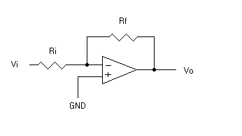
The following diagram shows the op-amp in a typical negative feedback
configuration.  Because we are assuming that
this is an ideal op-amp, if the positive input is grounded, so is the negative
input (remember that the output will change to force the input voltage
difference to zero). This leads us to the conclusion that the output voltage is
equal to the voltage across Rf, and the input is equal to the voltage across Ri.
Because we are assuming the input current to be zero, that means that the
current through Rf and the current through Ri must be equal, but of opposite
signs (remember from Kirchoff that the sum of all currents into a node must be
zero). We can therefore write the following equation:
        Vo/Rf = - Vi/Ri

        Which is more commonly written as:

        Vo = -(Rf/Ri)Vi
Note that if you do not assume the op-amp to be ideal, these equations become
a great deal more complicated.
Overall, this means that our circuit will multiply the input by -Rf/Ri to
create the output. Because of the negative sign, this is called an inverting
amplifier. The output will be the opposite sign from the input, and will be
scaled by the proportions of the two resistors.
The input impedence of this amplifier is simply Ri, since the inverted input
is effectively grounded.
Real World Op-amps
In the real world, op-amps do not have quite an infinite gain (100,000 to
1,000,000 is more typical), and they do draw a small amount of input current (a
few nano-amps). As long as you do not attempt to use circuits that are affected
by these less than perfect specs, you should not run into any difficulty.
Never attempt to use positive feedback. This will drive the op-amp
immediately into saturation, and your circuit will not work. If you need a
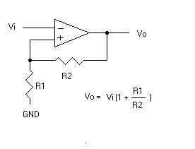
non-inverting amplifier, use a circuit like the following:  (note that the - and + terminals are reversed
from the previous circuit, otherwise this would be positive feedback)
In a practical circuit, do not attempt to use a feedback resistor that is too
low of a value, otherwise the op-amp will not be able to generate enough
feedback current to operate properly and strange things may result. A feedback
resistance of 1 meg is typical.
Note that most op-amps will not produce rail to rail (+V to -V) outputs, but
instead will start to clip at about 1.5 volts away from the supply. If you have
a +/- 9 volt supply, the output can't go more than +/- 7.5 volts.
A real world op-amp usually requires a bypass capacitor. This is a small
capacitor (a 0.1 uF ceramic usually works fine) placed between +V and -V, as
close to the chip as possible. This doesn't mean you need to sandwich the cap
under the chip, but typically it should be right next to the chip on the circuit
board. Sometimes your circuit will work fine without a bypass cap, but other
times it will howl and scream due to uncontrolled oscillations.
Your choice of op-amps will depend on your particular circuit requirements.
The basic 741 op-amp is one of the most popular chips in the world. It has a
reasonable performance and is very low cost, making it ideal for hobbyists. For
most audio circuits it works fine, but if you need better frequency response,
you may need to select something with slightly better characteristics (and a bit
larger price tag).
Using a battery
Op-amps require a dual voltage source. You can just use two batteries to
power the device, or you can be a bit clever and use only a single battery.
Remember that voltage is all relative. If you make a voltage divider out of two
resistors that are equal, the voltage in the middle will be half of the voltage
between the two ends. So, let's assume we have a 9 volt battery, and we connect
two 1 K resistors to the battery in series. The midpoint where the two resistors
connect to each other will be at 4.5 volts. What if we take this midpoint as our
voltage reference? In other words, we assume that this is our zero point. The
positive lead of the battery is therefore at +4.5 and the negative lead is -4.5
volts. Hmmm... sounds like a dual voltage power supply to me, eh?
In practical circuits, it is best to include bypass capacitors between this
midpoint and ground (0.1 uF ceramic caps will work fine for most circuits). This
helps to keep the reference at a stable voltage, so that it is not affected by
noise and signal variations.
A disadvantage of this method is that the resistors are always drawing power
just to create the voltage reference. In the above example, a 9 volt battery
connected to a 2k resistance (two 1k resistors in series) draws i=V/R=9/2K=4.5
mA.
If the external devices are drawing more current, smaller resistances may be
necessary to keep the voltage divider stable. This will, of course, increase the
amount of current required in the voltage divider. For most audio circuits (like
guitar effects) 1K works fine.
Op-Amp circuits
There are more practical circuits for op-amps than you can shake a stick at.
Obviously, I can't even hope to present them all here. So, here are just a few.
![]()
 Because we are assuming that
this is an ideal op-amp, if the positive input is grounded, so is the negative
input (remember that the output will change to force the input voltage
difference to zero). This leads us to the conclusion that the output voltage is
equal to the voltage across Rf, and the input is equal to the voltage across Ri.
Because we are assuming the input current to be zero, that means that the
current through Rf and the current through Ri must be equal, but of opposite
signs (remember from Kirchoff that the sum of all currents into a node must be
zero). We can therefore write the following equation:
  (note that the - and + terminals are reversed
from the previous circuit, otherwise this would be positive feedback)