This article covers the basics of power supplies, voltage and current sources, and the concept of internal resistance. It assumes that the reader is basically familiar with the concepts of voltage, current, and resistance.
Batteries make for a quick and easy power supply. Without any external components, they provide a clean, constant voltage. A typical battery is about 1.5 volts per cell. Batteries of higher voltages are constructed by simply connecting cells together in series. Thus, a 6 volt battery has four cells in series, and a 9 volt battery has six cells in series.
Batteries are nature's closest thing to an ideal voltage source. No matter what load you put on the battery, it will attempt to maintain a constant voltage at its terminals. If you try to draw too much current, though, the battery will reach its physical limits and the voltage at the terminals will start to drop. It's almost like the battery has its own internal resistor in series with its terminals.
Batteries are rated by their voltage, the amount of current they can supply, and how long they will last (the AH rating, for Amp-Hour). The voltage will be constant in your circuit. You want to be well under the maximum current rating of the battery. The amp-hour rating will tell you roughly how long the battery will last. Battery data books have actual discharge curves that you can use to determine exactly how long the battery will last in a given situation, but for almost all hobbyist applications the quick 'n' dirty AH method is close enough. Let's say, for example, that our battery is rated at 4 AH. This means it can supply 1 amp for 4 hours (1 amp times 4 hours equals 4 AH), or 2 amps for 2 hours, or 4 amps for one hour, or 1/2 amps for 8 hours, etc. Just multiply the current by the time to get the amp-hour. If you know the amp-hour and the current, you can divide to get the time. I usually include a safety factor by dividing the time result by 2, and figuring that I will have to change the battery then. For a lot of applications, this won't be off by more than 10 or 20 percent.
Typical battery data:
Type:                              Voltage   Max Current   AH Rating

AAA                                  1.5
AA                                   1.5
C                                    1.5
D                                    1.5
9V Transistor Battery                  9
6V Lantern Battery                     6
12V Car Battery                       12
Rechargable batteries are usually either Nickel-Cadmium (NiCd) or Lead Acid. Nickel-Cadmium (often called Ni-Cads) have a smaller voltage per cell than a regular battery, only 1.25 volts. AAA, AA, C, and D batteries will therefore be a slightly lower voltage than non-rechargable batteries. 9 volt transistor type batteries will either be made with the same number of cells (which means that the battery voltage will be only 7.5 volts) or may have an extra cell to bring the voltage up to 8.75 volts. NiCd batteries last longer when they are completely discharged and recharged. Lead acid batteries are usually damaged if they are completely discharged.
Sometimes we need more voltage or current than a single battery can provide. In this case, we simply need to connect more batteries together. If you connect the batteries in series (end to end) then each battery is going to attempt to maintain its voltage at its terminals, so the overall voltage will be the sum of the battery voltages. The same current flows through all of the batteries, so the maximum current of the whole set is the same as the maximum current of a single battery.
If we need more current, but the same amount of voltage, all we need to do is connect the positive terminals of all of the batteries together, and all of the negative terminals of the batteries together. They will all maintain their voltage across the terminals, so the overall voltage will be the same as that of any single battery, but the maximum current will be the sum of the maximum currents of each battery.
WARNING: Do not connect batteries of different voltages together in parallel. This may be obvious when you have a 12 volt car battery and a 1.5 volt AAA cell, but it also applies when you have a 1.5 volt D cell and a 1.25 volt Ni-Cad D cell.
Here's an example: Suppose we have 12 batteries, with each battery being 1.5 volts. Each battery can supply 1 amp maximum, but are only rated at 0.5 AH, and we want to get 2 hours out of our batteries, which means we want to limit them to 0.25 amps each. Our device that we are powering runs off of 6 volts and draws 1 amp. Will these batteries work?
Answer: The batteries are 1.5 volts each, which means we need 4 batteries in series to make 6 volts. Since we have 12 batteries, we can make 3 sets of 4 batteries in series, and put all 3 sets in parallel. Each set can supply up to 0.25 amps (for our 2 hour battery life). Our total current is therefore 3(0.25) or 0.75 amps maximum. This is less than 1 amp, so the batteries will not have enough current for our application. We need 4 more batteries, so that we could make 4 parallel sets of four series batteries each.
In summary, if you need more voltage, put more batteries together in series. If you need more current, put more batteries together in parallel. If you need more voltage and current, you can combine batteries both in series and in parallel.
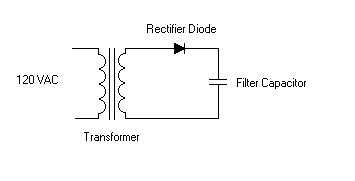
AC is not particularly useful in electronics, where you usually need a constant voltage source. A typical power supply, like what you might find in your stereo or VCR, has a transformer to drop the voltage down to the desired level. The power is then fed through a rectifier and a filter, which converts the AC to DC.

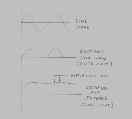
The rectifier is a diode. Diodes are discussed in detail in another chapter, but briefly, it allows current to flow in one direction but not another. This cuts off the negative portion of the AC sine wave. Adding a capacitor filters this signal, so that the output of the circuit is fairly close to a constant voltage. The output is not perfect, though, due to the fact that the capacitor cannot completely filter off the variations in the input signal. The amount that the output varies from true DC is called the ripple. In general, we want the ripple to be as small as possible, which is done by making the capacitor as large as is practical for the circuit. Very often a small ceramic disc capacitor (0.1 uF) is placed in parallel with a larger electrolytic (1000 uF) capacitor. The large electrolytic does most of the filtering work, and the small ceramic capacitor is used to filter off high frequency noise that might cause interference in the circuit.
A full wave rectifier uses 4 diodes (called a full wave bridge) which always
allows a path for the current to go, whether the voltage is positive or
negative. This is more effecient than a single diode rectifier, since the
negative swing of the AC wave is also utilized. 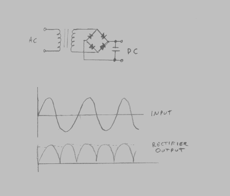
Often we need both a positive and a negative supply in a circuit (this is
typical of analog circuits). Making a dual supply using batteries is trivial -
you just use two batteries. Using a center tapped transformer, this can be
easily done for AC driven supplies as well. 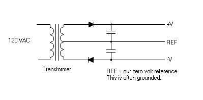
A fuse is a device that is placed in series with a circuit. When the current through the circuit (and hence through the fuse) becomes too great, the fuse is destroyed, causing the circuit to open up, which prevents further current from flowing and damaging the circuit components. Fuses come in a wide variety of types. Most common are the glass fuses, which have a small conductive filiment encased in a glass tube with conductive surfaces on each end of the fuse. The glass allows you to look at the delicate filiment without touching it, so that you can see if it is blown. If the filiment looks damaged, is broken, or (if enough current has gone through the fuse) it has been completely blown away and all you can see is the glass, then you need to replace the fuse.
Automobiles typically will use blade type fuses. These have the fuse element in a little plastic case, with two conductive blades sticking out that connect the fuse into the fuse box. The same principles apply as with glass type fuses, only the fuse element may be more difficult to see.
Another type of fuse, also often seen in automobiles, is what is called a fusable link. In this case, a smaller wire, sized to only adequately carry the maximum amount of current for normal operating conditions, is put in series with much larger sized wire, which actually carries the current to the device. If too much current flows, the smaller wire will burn out first.
IMPORTANT NOTE: Fuses are very low tolerance devices. A 1 amp fuse may blow with as little as 0.8 amps going through it, or it may take significantly more than 1 amp (maybe 1.4 amps, for example) to blow it. Therefore, use fuses with caution in your design. I made a mistake early in my electronics career where I sized the fuse too close to the operating limits of the voltage regulator it was trying to protect (basically, because I was trying to force too much current out of the regulator). I had 3 failures while developing the device. In all three cases, the regulator blew, leaving the fuse intact. Obviously, I had not sized my fuse appropriately.
Transformers are readily available in a variety of voltages, typically 3, 6, 9, 12, 18, and 24 volts AC (with 120 VAC input). The transformer needs to be capable of supplying all of the current your circuit needs, plus all of the current that is wasted due to ineffeciency in your rectifier/filter circuit. As a general rule, you don't want to push any part of your circuit, including transformers, up to its maximum limits. This causes parts to overheat and fail much more quickly than they would if not so stressed.
Diodes must be capable of handling the current passing through them also. Diodes marketted as power diodes will usually have plenty of current capability.
Capacitors are rated by their value (in microfarads) and their maximum voltage. If you are making a 12 volt power supply, you will want to use capacitors rated for at least 24 volts (well in excess of 12).
Here are some complete circuits, showing the power switch, fuses, and noise
filtering capacitors. 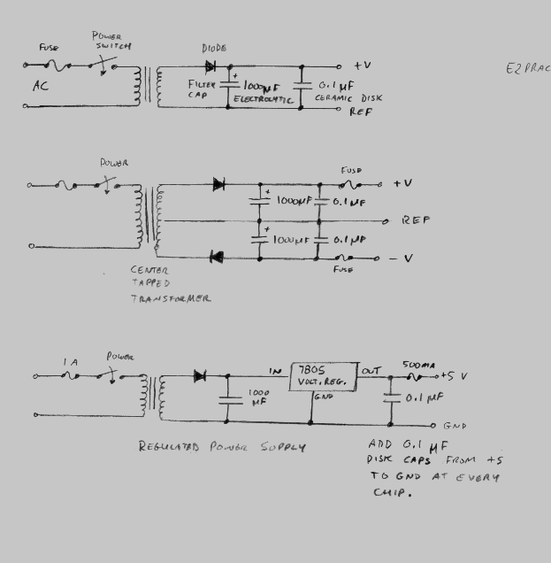
A "wall wart" is a small power supply that usually looks like a little black box with prongs that plug into an AC outlet. The wall wart has the AC transformer and the AC to DC circuit all built into the box, so they make for quick and simple supplies. Wall warts are cheap, are a little on the skimpy side with respect to filtering, and do not have good voltage regulation (the output may be higher or lower than what you expect). You may need to add a bit of filtering or regulation to your own circuit if you plan on driving it off of this type of supply. Be careful! Wall warts do not generally have a lot of protection from overcurrents. If you try to draw too much current, you will often damage the power supply.