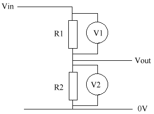
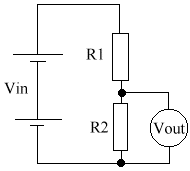
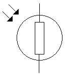
The potential divider is used to give a reduced voltage. It divides in the same ratio as the resistors. They can seem quite complex at first, but they're really not that difficult once you get the hang of them.
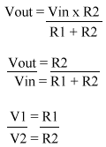
There are many formulas relating to the potential divider.
12. Measuring Potential Dividers
Vin (V)
R1
R2
Calculated Vout
Measured Vout
10
4K7 1KO 1.75
1.71
10
2K2 3K3 6
5.77
10
10K 5K6 3.5
3.64
10
3K 1K 3
2.77
12
6K 1K 2
1.77
10
1K59 1K 6.3
6.34
13. Using different voltmeters
- Both meters measured accurately across the 22K but the moving coil meter was inaccurate across the 220K.
- This is because the moving coil meter has a resistance of only 220K, & therefore takes a significant current from the 220K circuit. It is therefore changing the voltage it is measuring.
- The digital voltmeter has a resistance of 10M, which is very high. It therefore takes an insignificant current from either circuit.
- The resistance of the meter is an important advantage of a digital voltmeter when used in high resistance circuits.
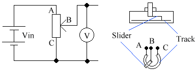
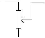
A potentiometer is a variable potential divider. Below is the circuit diagram, & a diagram of its construction. The idea is that you move a slider along a track (it's normally a coil), and depending on the poistion on the coil, the resistance will vary between each side.
Presume Vin is set at 10V.
- If slider is set at A, then V = 10V.
- If slider is set at B, then V = 5V.
- If slider is set at C, then V = 0V.
Any voltage between Vin & 0V is obtainable.
There are 2 types of potentiometer:
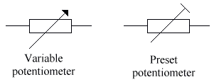
Both can be used as a variable resistor, by only connecting 2 of the terminals.
15. The Light Dependent Resistor
The resistance of the LDR (Light Dependent Resistor) falls as the brightness increases.
