When an indicator is needed, the practical choices are either a lightbulb, or an LED. Here is a comparison.
LED
Lightbulb
Low current required (5mA) High current required (60mA) Robust Fragile Lasts indefinitely Filament slowly evaporates Immediate response Much slower response Gives coloured light Produces white light
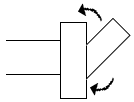
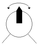
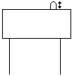
There are many types of switch. Note that these pictures are not circuit diagrams. There is no way of specifying which switch to use for a circuit. It comes down to common sense.
These are either on/off, or are biased, so they spring back into place after being released.
These are either normally on (push-to-break), or normally off (push-to-make). They can be latched, so they stay pressed down after you remove your finger, like the switches on a torch.
These are magnetically activated.
The mercury flows inside, & when the switch is tilted a certain way, it will connect the 2 contacts. In the above illustration, it's shown in the closed position.
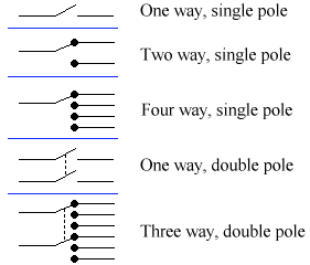
In electronics, a way is a number of switch positions. A pole is the number of switches moved together.
Sometimes this is written in a kind of shorthand. Here's an example of the four types you're most likely to meet.
SPST Single Pole, Single Throw SPDT Single Pole, Single Throw DPST Double Pole, Single Throw DPDT Double Pole, Double Throw These are the only widely used shorthand abbreviations, as these are the most widely used switches.
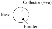
The transistor is basically a glorified switch. It is also a driver, enabling you to power components that normally require a much higher current.
It's very easy to make these little dudes blow up. If you do electronics in school, they'll tell you - "These things blow up easily". It's not as much fun as it sounds. They just emit a little puff of smoke. They're not dangerous at all. They couldn't damage a thing. They may draw a little blood, but your limbs are safe. But don't put too much current through them, or they'll blow up.
Transistors are one of the most difficult subjects in electronics - so don't worry if you need to re-read some of this stuff.
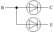
The NPN transistor appears to contain 2 diodes. They are wired as so:
For that reason, the transistor has a turn-on voltage of 0.7V.
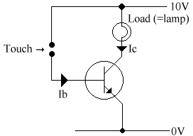
Experiment to turn a lamp on by touch
Normally there is no collector current (Ic), but if we provide the base with a very small base current (Ib), which we can do by touching the terminals, a much larger Ic is permitted to flow.
The current gain is called the hFE. Normally the FE is written in subscript. It is calculated by Ic / Ib. Most transistors have an hFE of about 250 - 400.
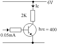
Another term related to transistors is the saturation current. When a transistor is saturated, the collector current has reached the maximum, & is no longer controlled by the base current (ie. It doesn't matter how much current you pump in, it will give the same Ic). The Saturation current = Vcc / R. For example:
hFE = Ic / Ib so therefore Ic = Ib * hFE
= 0.05 * 400 = 20mA
But Ic (saturation) = 6 / 2 = 3mA. The transistor is saturated.
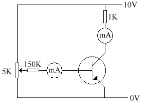
Experiment to determine the current characteristic of a transistor & find its hFE.
Ic (mA)
Ib(uA)
1 2.5 2 4.8 3 7.1 4 9.4 5 13.7 6 14.1 7 16.8 8 19.6 9 22.8
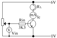
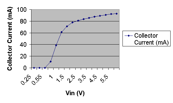
Vin (V) Ic (mA) 0.5 0 1.0 38.5 1.5 71.3 2.0 77.6 2.5 81.1 3.0 83.6 3.5 85.8 4.0 87.7 4.5 89.4 5.0 90.8 5.5 92.1 5.95 93.0 0.75 10.8 0.25 0 1.25 61.1 0.55 0.01 Note that the results above are not in order. Specifically, there are a couple of extra results on the end.
The transistor can be used as a buffer, or as a digital switch (<0.7V, the switch is off, >0.7, the switch is on). The transistor often becomes saturated.
When Vin is 0V, the transistor is off, so the lamp is off. For all values of Vin <0.7V, the transistor is off because the base current will be 0mA (due to the diode).
If Vin is greater than 0.7V, a base current flows & the transistor starts to come on. In the case of the previous experiment, it was fully on from about 1.5V (ie. The transistor was saturated).
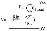
The load (RL) could be a lamp, a buzzer, a motor, a solenoid, etc, etc.
Rin limits the current flowing into the base. It should be as high as possible, while still saturating the transistor.
The Field Effect Transistor (FET)
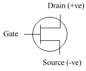
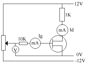
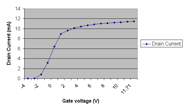
The field effect transistor is a little bit different, in the form of it needs no gate current, only a gate voltage. Also, it's turn on voltage is below zero, which makes it a pain to wire but can be useful in places.
Voltage (Gate) Ig Id -11.7 0 0 -10 0 0 -9 0 0 -8 0 0 -7 0 0 -6 0 0 -5 0 0 -4 0 0 -3 0 0 -2 0 0.8 -1 0 3.16 0 0 6.4 1 0 8.95 2 0 9.65 3 0 10.1 4 0 10.42 5 0 10.67 6 0 11.85 7 0 11.01 8 0 11.12 9 0 11.23 10 0 11.31 11 0 11.38 11.7 0 11.42
FET NPN bipolar Voltage controlled Current Controlled Negative turn-off voltage Turns off <0.7V Input current Ig is 0 Higher input current (Ib)
MOSFET stands for Metal Oxide Silicon Field Effect Transistor. Which means as much to you as it does to me. It's basically a description of it's construction, & is a very trivial piece of trivia.You don't need to know what it stands for. It's normally used as a driver following a gate circuit.
MOSFET NPN Can switch on large load currents. Cheaper. Requires less input current. Has a definite switch-on voltage.
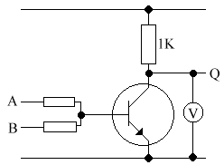
A B Q 0V 0V 9.98V 0V 10V 0.5V 10V 0V 0.5V 10V 10V 0.5V It is a NOR gate, as it gives a logic 1 when A&B are 0, & logic 0 when A or B are 1.
When A is low, Ib is also low. There will be no voltage across the 1K transistor, so all the voltage must go to Q.
An integrated circuit is the correct name for a chip. It consists of several transistors, resistors, etc. made on a single piece of silicon (a silicon chip). We use IC's for a number of reasons:
- Smaller (more compact)
- Cheaper
- We don't need to know how it works, only how to wire it.
- Faster
- Less soldering, so a more reliable circuit.
There are two types of IC:
TTL CMOS Very fast Quite fast Needs about 1mA per gate. Requires negligible current. Needs exactly 5V ± 0.25V. Works using any pd between 3V & 18V.
The relay is an electrically operated switch. It is represented using the following symbol:
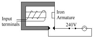
And is constructed as follows:
A small voltage applied to the input terminals (eg. 12V) applied to the input terminals activates the electromagnet, & closes the contacts. These contacts can then switch on larger amounts of current & voltage safely.
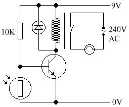
It can be used to enable transistors or IC circuits to switch on higher voltage or current components. For example, an automatic porch lamp:
The porch lamp comes on automatically in the dark.
The diode, which is reversed biased, must always be in place, as it protects the transistor against short short, high-voltage pulses when it switches off.
To adjust the sensitivity, change the 10K resistor. A higher resistance makes it more sensitive, & a lower makes it less.
