This is advanced logic - if you don't know about the normal logic, you
don't have a hope of understanding this. So go & get acquainted by
clicking here.If
you feel you already understand logic, or are too stubborn to take my
advice, then continue. From now on, it gets a little more complicated.
The latch is a handy piece of logic & circuitry to know - but it's
very confusing if you try to figure it out. It's easier to explain if we use
an example. So let's use a burglar alarm.
OK. You are a person who has decided to create a burglar alarm for his
house. You're going to get it to trigger by placing a touchpad under the
doormat, that gives a logic 1 when trodden on. You've already designed the
logic circuit to set the alarm off if the circuit receives a logic 1 from
the touchpad AND a logic 1 from the control panel when it is set (another
system that you have already designed). So you wire up your ciruit, set it,
and go out. By an astonishing coincidence, a burglar breaks in. And by
another astonishing coincidence, the burglar breaks in using the door. he
takes a step in, & treads on the touchpad. Your AND circuit will give a
logic 1, and set the alarm off. "Oh dear" thinks the burglar, and he runs
off.
As soon as he takes his foot off the pad, the logic gate will
automatically give a logic 0, because it no longer recieves a logic 1 from
both inputs. Thus the alarm promptly turns itself off. "Yipee!" thinks the
burglar, steps over your doormat, and rids you of your worldly
possessions.
So, how do you prevent this happening? You need the alarm to stay on when
the AND gate gives a 0 when it was previously given a 1. You do this using a
latch, which will 'latch on' when there is a logic 1 to it. It's a bit like
those switches, which stay down until you press it again. Before we look at
the two types of latch, you must learn about a new symbol - Q with a bar
over it. I can't type it, but you'll see it on the diagrams below. It means
NOT Q.
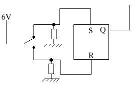
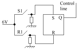
From NOR gates
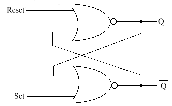
If R = 1 & S = 0 then Q = 0, ie. It is reset.
If R = 0 & S = 1
then Q = 1, ie. It is set.
If R = 0 & S = 0 then Q can be either 0 or
1, depending on whether R or S was previously equal to 1. This is known as
the memory state.
From NAND gates
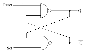
If R = 1 & S = 1 then Q = 0 or 1 - it is in the memory state.
If R
= 0 & S = 1 resets Q to 0
If R = 1 & S = 0 sets Q to 1
This is known as sequential logic. This means that the output value
depend on the previous states of the input.
The memory state stores the previous output. For example, if Q = 1 in a
NOR gate from R = 0 and S = 1, and then R & S were both set to 0, the
output would remain 1. But if the previous state was a 0, from a R = 1 and
an S = 0, and then it was set to the memory state, it would remain 0. This
is how computer memory works.
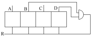
The Memory
Register
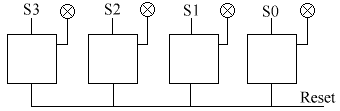
Before we get into this, the little circles with a cross inside them are
indicators.They're just symbolic representation - don't use them in cicuit
diagrams. The only reason they're used here is for simplicity. All the S's
are the Sets.
In this, we are using 4 bistables. We want to remember the number 5,
which in binary (if you don't understand binary, click here)
is 0101. What do we have to do to set it to 0101? The not very perceptive
would say that you apply a logic 1 to S0 &S2. But what if S1 & S3
were previously set to 1? Then your circuit will read 15. Which is not what
we want. So, we have to reset all bistables, apply logic 1 to S0 & S2,
and set all the S's to 0.
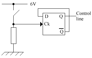
The D-Type (Data Type)
bistable

This is also sometimes known as a flip-flop. It has a couple of new
things that you haven't seen before: A clock (Ck) & a Data (D) input. Q
will become equal to D on the falling edge of the clock pulse (ie. When the
Ck goes from 1 to 0).
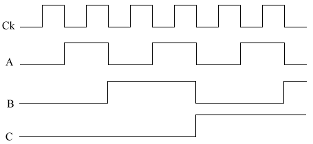
The timing diagram.
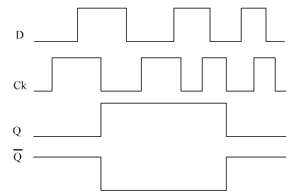
We draw in the Ck & the D, and presume that Q starts at 0. We then
draw the predictions (See example below).
What happens if Q bar is connected to D?
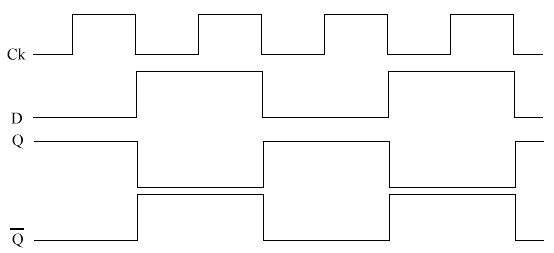
What happens is that whenever Ck goes from 1-0, Q changes state. This is
known as a toggle. Note that this is happening at half the frequency of the
clock.
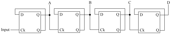
Counting circuit
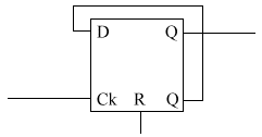
As many of these blocks can be added as neccessary(see below).
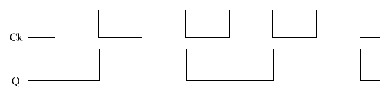
The Binary up
counter