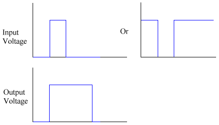
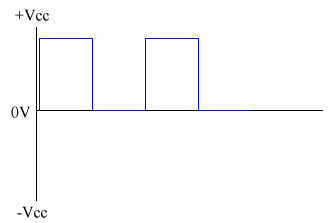
This is also known as a triggered pulse producer. Once triggered by an input voltage, it gives a fixed length output pulse. It will do this for even short input pulses. This can be put to good effect in many applications. The best example is for a burglar alarm, that will sound for 20 minutes and then turn itself off. Below is a block diagram for a monostable and a timing diagram for it.
- Burglar alarms - to keep the alarm on for a certain time
- Egg timer
- Switch de-bouncing
32. The 555 timer as a monostable
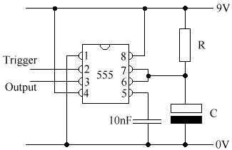
It is possible to use the 555 timer as a monostable as well as an astable. To do so, we use this circuit:
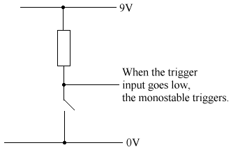
We could use this circuit to trigger the monostable. The loose line by the text would be connected to the Trigger of the 555.
The time period for a monostable = 1.1 x R x C. Make sure you always work in Ohms and Farads.
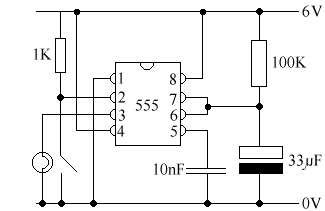
We can create a monostable with very little alterations to the above circuit. This circuit below will serve us perfectly.
Time period of monostable = 1.1 x R x C = 1.1 x 100000 x 0.000033 = 3.63s
We measured the time period using an oscilloscope to be 5s.
33. Alarms
You may remember that right back at the beginning of this tutorial, we dealt with systems. Now you know about the components, we can look at some more advanced systems.
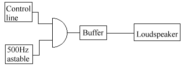
The alarm above will sound when the control line is a logic 1.
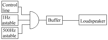
This alarm will give a pulse at 500 Hz once a second, if the control line is a logic 1. This is how it is produced in almost all circuits - you can bolt on any circuit to the control line and it will sound the alarm.
34. Alternating voltage and current (AC)
AC is what you get out of the mains, rather than DC, which you get out of the battery. Almost all circuits are DC, even those run off the mains - they normally have some circuitry that lets them convert the AC to DC. Here in the UK, our supply runs at 50Hz. If you're across the pond in America, then your supplies are 60Hz. There's nothing better about either of them, but it's a pain in the neck to run certain pieces of equipment in the country other than it was designed for, like videos, TVs, and computer monitors.
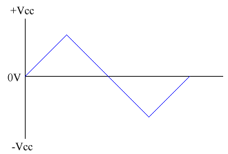
- Sine wave - eg. mains electricity. In the UK, it is 240Vrms, 50 Hz. ThisVrms is explained below.
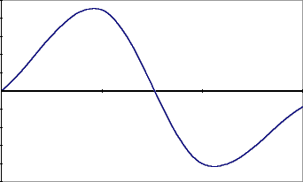
- Peak voltage (Vp) = amplitude.
- Peak to Peak voltage (Vpp) = 2 * Vp.
- Root Mean Square voltage (Vrms) - this is the normally quoted voltage or current. Voltmeters or ammeters read this. We cannot quote an average as the average will be 0. We don't want to use Vp, as the voltage is only at this value for a tiny amount of time, and so we cannot use it for power and other equations. Vrms = SQRT(average of V2). SQRT() is a way of saying square root without the sign.
V2 is always poisitive, and thus so is the average of it. We can now use the standard power equations. The formula above will work for all AC waveforms. These two won't:
Vrms = Vp / SQRT(2)
Irms = Ip / SQRT(2)If you've got a calculator handy, you can use the sqare root button on it to get the value. If not, it's about 1.44, so you can use that to do the calculation in your head.
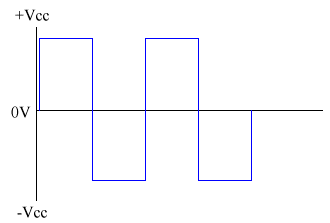
Note that this is not the same as a square wave, as the Astable never drops below 0V.

