[Diode Logic (DL)]
[Resistor-Transistor Logic (RTL)]
[Diode-Transistor Logic (DTL)]
[Transistor-Transistor Logic (TTL)]
[Emitter-Coupled Logic (ECL)]
[CMOS]
As we said in the page on diode logic, the basic problem with DL gates is that they rapidly deteriorate the logical signal. However, they do work for one stage at a time, if the signal is re-amplified between gates. Diode-Transistor Logic (DTL) accomplishes that goal.

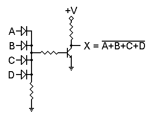
The gate to the right is a DL OR gate followed by an inverter such as the one we looked at in the page on resistor-transistor logic. The OR function is still performed by the diodes. However, regardless of the number of logic 1 inputs, there is certain to be a high enough input voltage to drive the transistor into saturation. Only if all inputs are logic 0 will the transistor be held off. Thus, this circuit performs a NOR function.
The advantage of this circuit over its RTL equivalent is that the OR logic is performed by the diodes, not be resistors. Therefore there is no interaction between different inputs, and any number of diodes may be used. A disadvantage of this circuit is the input resistor to the transistor. Its presence tends to slow the circuit down, thus limiting the speed at which the transistor is able to switch states.

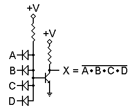
At first glance, the NAND version shown on the left should eliminate this problem. Any logic 0 input will immediately pull the transistor base down and turn the transistor off, right?
Well, not quite. Remember that 0.65 volt base input voltage for the transistor? Diodes exhibit a very similar forward voltage when they're conducting current. Therefore, even with all inputs at ground, the transistor's base will be at about 0.65 volt, and the transistor can conduct.

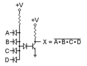
To solve this problem, we can add a diode in series with the transistor's base lead, as shown to the right. Now the forward voltage needed to turn the transistor on is 1.3 volts. For even more insurance, we could add a second series diode and require 1.95 volts to turn the transistor on. That way we can also be sure that temperature changes won't significantly affect the operation of the circuit.
Either way, this circuit will work as a NAND gate. In addition, as with the NOR gate, we can use as many input diodes as we may wish without raising the voltage threshold. Furthermore, with no series resistor in the input circuit, there is less of a slowdown effect, so the gate can switch states more rapidly and handle higher frequencies. The next obvious question is, can we rearrange things so the NOR gate can avoid that resistor, and therefore switch faster as well?

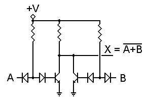
The answer is, Yes, there is. Consider the circuit shown to the left. Here we use separate transistors connected together. Each has a single input, and therefore functions as an inverter by itself. However, with the transistor collectors connected together, a logic 1 applied to either input will force the output to logic 0. This is the NOR function.
Incidentally, this same approach can be used for RTL NOR/OR gates, so that the NOR operation is performed at the transistor collectors rather than using resistors to OR multiple signals together. This approach also eliminates the limit on the number of inputs that can be handled, since now there is no interaction between inputs.
[Diode Logic (DL)]
[Resistor-Transistor Logic (RTL)]
[Diode-Transistor Logic (DTL)]
[Transistor-Transistor Logic (TTL)]
[Emitter-Coupled Logic (ECL)]
[CMOS]
Go to the Logic Family base page.