Combinational Logic:
[Basic Gates]
[Derived Gates]
[The XOR Function]
[Binary Addition]
[Multiplexer]
[Decoder/Demultiplexer]
Sequential Logic:
[RS NAND Latch]
[Clocked RS Latch]
[RS Flip-Flop]
[JK Flip-Flop]
[D Latch]
[Flip-Flop Symbols]
Counters:
[Basic 4-Bit Counter]
Registers:
(Coming Soon)
Return to Digital index page.
Return to Play-Hookey Home Page.
Although the internal circuitry of latches and flip-flops is interesting to watch on an individual basis, placing all of those logic symbols in a diagram involving multiple flip-flops would rapidly generate so much clutter that the overall purpose of the diagram would be lost. To avoid this problem, we use the "black-box" approach. This is actually just one step further that the "black-box" approach we used in specifying logic gate symbols to represent specific clusters of electronic components — now we are using on symbol to represent a cluster of logic gates connected to perform a specific function.
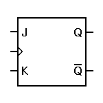
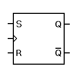
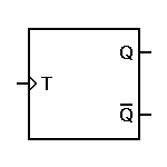
Some typical flip-flop symbols are shown below:
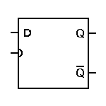
As you have no doubt noticed, the symbols above are nearly identical — only the inputs vary. This is typical of the "black-box" approach. However, there is one other variation, as shown to the right.
In each of the symbols above, the clock input is marked by the small angle, rather than by the letters CLK. That little angle marker actually provides two pieces of information, rather than one. First, of course, it marks the clocking input. Second, it specifies that these are edge-triggered flip-flops. The D latch shown to the right uses a rounded marker for the clock input. This signifies that the circuit is controlled by the clock level, not the clock edge. In fact, the symbol to the right would normally be used for the D latch circuit shown separately. If we change that rounded input to a sharp angle, it would indicate an edge-triggered master-slave D flip-flop.
Any of these symbols may be modified according to their actual use within the larger circuit. For example, if only the Q output is used, it may well be the only output shown. Some flip-flops incorporate master preset or reset inputs, which bypass the clock and the master section of an edge-triggered flip-flop and force the output to an immediate known state. This is often used when a circuit comprised of many flip-flops is first powered up, so that all circuits will start in a known state.
It is very seldom that a flip-flop will actually be used alone. Such circuits are far more useful when grouped together and acting in concert. There are two general ways in which flip-flops may be interconnected to perform useful functions: counters and registers. In the next series of pages, we'll start with counters and then look at registers.
|
|
|
|
| The D Latch | Return to Digital Page | To Counters |