|
|
 |
Combinational Logic:
[Basic Gates]
[Derived Gates]
[The XOR Function]
[Binary Addition]
[Multiplexer]
[Decoder/Demultiplexer]
Sequential Logic:
[RS NAND Latch]
[Clocked RS Latch]
[RS Flip-Flop]
[JK Flip-Flop]
[D Latch]
[Flip-Flop Symbols]
Counters:
[Basic 4-Bit Counter]
Registers:
(Coming Soon)
Return to Digital index page.
Return to Play-Hookey Home Page.
To prevent any possibility of a "race" condition occurring when both the S and R inputs are at logic 1 when the CLK input falls from logic 1 to logic 0, we must somehow prevent one of those inputs from having an effect on the master latch in the circuit. At the same time, we still want the flip-flop to be able to change state on each falling edge of the CLK input, if the input logic signals call for this. Therefore, the S or R input to be disabled depends on the current state of the slave latch outputs.
If the Q output is a logic 1 (the flip-flop is in the "Set" state), the S input can't make it any more set than it already is. Therefore, we can disable the S input without disabling the flip-flop under these conditions. In the same way, if the Q output is logic 0 (the flip-flop is Reset), the R input can be disabled without causing any harm. If we can accomplish this without too much trouble, we will have solved the problem of the "race" condition.
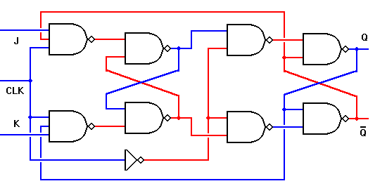
The circuit below shows the solution. To the RS flip-flop we have added two new connections from the Q and Q' outputs back to the original input gates. Remember that a NAND gate may have any number of inputs, so this causes no trouble. To show that we have done this, we change the designations of the logic inputs and of the flip-flop itself. The inputs are now designated J (instead of S) and K (instead of R). The entire circuit is known as a JK flip-flop.
|
|
 |
In most ways, the JK flip-flop behaves just like the RS flip-flop. The Q and Q' outputs will only change state on the falling edge of the CLK signal, and the J and K inputs will control the future output state pretty much as before. However, there are some important differences.
Since one of the two logic inputs is always disabled according to the output state of the overall flip-flop, the master latch cannot change state back and forth while the CLK input is at logic 1. Instead, the enabled input can change the state of the master latch once, after which this latch will not change again. This was not true of the RS flip-flop.
If both the J and K inputs are held at logic 1 and the CLK signal continues to change, the Q and Q' outputs will simply change state with each falling edge of the CLK signal. (The master latch circuit will change state with each rising edge of CLK.) We can use this characteristic to advantage in a number of ways. A flip-flop built specifically to operate this way is typically designated as a T (for Toggle) flip-flop. The lone T input is in fact the CLK input for other types of flip-flops.
The JK flip-flop must be edge triggered in this manner. Any level-triggered JK latch circuit will oscillate rapidly if all three inputs are held at logic 1. This is not very useful. For the same reason, the T flip-flop must also be edge triggered. For both types, this is the only way to ensure that the flip-flop will change state only once on any given clock pulse.
Because the behavior of the JK flip-flop is completely predictable under all conditions, this is the preferred type of flip-flop for most logic circuit designs. The RS flip-flop is only used in applications where it can be guaranteed that both R and S cannot be logic 1 at the same time.
At the same time, there are some additional useful configurations of both latches and flip-flops. In the next pages, we will look first at the major configurations and note their properties. Then we will see how multiple flip-flops or latches can be combined to perform useful functions and operations.
|
|
|
|
| The RS Flip-Flop | Return to Digital Page | The D Latch |