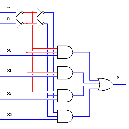
The multiplexer concept is not limited to two data inputs. If we add a second addressing input, B, we can control as many as four data inputs, as shown to the left. A third and fourth addressing input will allow the multiplexer to control eight or sixteen inputs, respectively.
Please allow a little time for this interactive demonstration to load. It requires 64 separate images, each approximately 4K.
Inputs A and B are the addressing inputs to this multiplexer. They select which of the four data inputs will be transmitted to the final output, X. If the data inputs are to be multiplexed for transmission to a distant location, the inputs must cycle through all four possible addreses more than twice for each single cycle of each of the data inputs. Otherwise the input data cannot be reconstructed accurately at the receiving end.