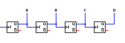
In the 4-bit counter to the right, we are using edge-triggered master-slave flip-flops similar to those in the Sequential portion of these pages. The output of each flip-flop changes state on the falling edge (1-to-0 transistion) of the T input.

Combinational Logic:
[Basic Gates]
[Derived Gates]
[The XOR Function]
[Binary Addition]
[Multiplexer]
[Decoder/Demultiplexer]
Sequential Logic:
[RS NAND Latch]
[Clocked RS Latch]
[RS Flip-Flop]
[JK Flip-Flop]
[D Latch]
[Flip-Flop Symbols]
Counters:
[Basic 4-Bit Counter]
Registers:
(Coming Soon)
Return to Digital index page.
Return to Play-Hookey Home Page.
One common requirement in digital circuits is counting, both forward and backward. Digital clocks and watches are everywhere, timers are found in a range of appliances from microwave ovens to VCRs, and counters for other reasons are found in everything from automobiles to test equipment.
Although we will see many variations on the basic counter, they are all fundamentally very similar. The demonstration below shows the most basic kind of binary counting circuit.
|
|
|
|
| To Sequential Circuits | Return to Digital Page | To Counters |