The 1-to-2 Line Decoder/Demultiplexer

Direct links to other logic pages:


Combinational Logic: [Basic Gates] [Derived Gates] [The XOR Function] [Binary Addition] [Multiplexer] [Decoder/Demultiplexer]
Sequential Logic: [RS NAND Latch] [Clocked RS Latch] [RS Flip-Flop] [JK Flip-Flop] [D Latch] [Flip-Flop Symbols]
Counters: [Basic 4-Bit Counter]
Registers: (Coming Soon)


Return to Digital index page.
Return to Play-Hookey Home Page.

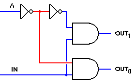
The opposite of the multiplexer circuit, logically enough, is the demultiplexer. This circuit takes a single data input and one or more address inputs, and selects which of multiple outputs will receive the input signal. The same circuit can also be used as a decoder, by using the address inputs as a binary number and producing an output signal on the single output that matches the binary addres input. In this application, the data input line functions as a circuit enabler — if the circuit is disabled, no output will show activity regardless of the binary input number.

A one-line to two-line decoder/demultiplexer is shown below.


1-to-2-line decoder/demultiplexer

This circuit uses the same AND gates and the same addressing scheme as the two-input multiplexer circuit shown in these pages. The basic difference is that it is the inputs that are combined and the outputs that are separate. By making this change, we get a circuit that is the inverse of the two-input multiplexer. If you were to construct both circuits on a single breadboard, connect the multiplexer output to the data IN of the demultiplexer, and drive the (A)ddress inputs of both circuits with the same signal, you would find that the initial X0 input would be transmitted to OUT0 and the X1 input would reach only OUT1.

The one problem with this arrangement is that one of the two outputs will be inactive while the other is active. To retain the output signal, we need to add a latch circuit that can follow the data signal while it's active, but will hold the last signal state while the other data signal is active. An excellent circuit for this is the D (or Data) Latch. By placing a latch after each output and using the Addressing input (or its inverse) to control them, we can maintain both output signals at all times. If the Address input changes much more rapidly than the data inputs, the output signals will match the inputs faithfully.

Like multiplexers, demultiplexers are not limited to two data signals. If we use two addressing inputs, we can demultiplex up to four data signals. With three addressing inputs, we can demultiplex eight signals. The demonstration of the 2-to-4 line decoder/demultiplexer is much smaller than the demo for the four-input multiplexer, because it has fewer independent input signals. With one data input and two addressing inputs, the decoder/demultiplexer only needs 8 images for the full demonstration.


Previous Digital Index Next
The Binary Adder Return to Digital Page To Sequential Logic
Back to the Play-Hookey main page.