The Two-Input Multiplexer

Direct links to other logic pages:


Combinational Logic: [Basic Gates] [Derived Gates] [The XOR Function] [Binary Addition] [Multiplexer] [Decoder/Demultiplexer]
Sequential Logic: [RS NAND Latch] [Clocked RS Latch] [RS Flip-Flop] [JK Flip-Flop] [D Latch] [Flip-Flop Symbols]
Counters: [Basic 4-Bit Counter]
Registers: (Coming Soon)


Return to Digital index page.
Return to Play-Hookey Home Page.

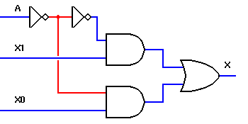
One circuit I've received a number of requests for is the multiplexer circuit. This is a digital circuit with multiple signal inputs, one of which is selected by separate address inputs to be sent to the single output. It's not easy to describe without the logic diagram, but is easy to understand when the diagram is available.

A two-input multiplexer is shown below.


Two-Input Multiplexer

The multiplexer circuit is typically used to combine two or more digital signals onto a single line, by placing them there at different times. Technically, this is known as time-division multiplexing.

Input A is the addressing input, which controls which of the two data inputs, X0 or X1, will be transmitted to the output. If the A input switches back and forth at a frequency more than double the frequency of either digital signal, both signals will be accurately reproduced, and can be separated again by a demultiplexer circuit synchronized to the multiplexer.

This is not as difficult as it may seem at first glance; the telephone network combines multiple audio signals onto a single pair of wires using exactly this technique, and is readily able to separate many telephone conversations so that everyone's voice goes only to the intended recipient. With the growth of the Internet and the World Wide Web, most people have heard about T1 telephone lines. A T1 line can transmit up to 24 individual telephone conversations by multiplexing them in this manner.

A very common application for this type of circuit is found in computers, where dynamic memory uses the same address lines for both row and column addressing. A set of multiplexers is used to first select the row address to the memory, then switch to the column address. This scheme allows large amounts of memory to be incorporated into the computer while limiting the number of copper traces required to connect that memory to the rest of the computer circuitry. In such an application, this circuit is commonly called a data selector.

Multiplexers are not limited to two data inputs. If we use two addressing inputs, we can multiplex up to four data signals. With three addressing inputs, we can multiplex eight signals. If you would like to see a demonstration of a four-input multiplexer, you can follow this link. This demonstration requires 64 separate images, each approximately 4K bytes in size, so it will take a little while to load. For this reason, it is not included in the list of digital pages at the top of each page. An eight-input multiplexer would require either 2048 separate images or a rather complex implementation of dynamic HTML; therefore it will not be included on these pages.

Previous Digital Index Next
The Binary Adder Return to Digital Page To Sequential Logic
Back to the Play-Hookey main page.